
Most people who go looking for metal stamping are not actually shopping for a press. They are holding a part that has to be made repeatably, in a quantity that makes hand fabrication awkward, at a landed cost that still leaves margin after finishing, assembly, and freight. In display-mounting hardware, that part is usually a wall plate, a VESA bracket, a tilt housing, an arm link, a riser foot, or one of the small formed clips and retainers that hold the whole assembly together. The question underneath “can you stamp this” is almost never metallurgical. It is: does this geometry, at this volume, with this finish and this tolerance stack, belong on a stamping route at all, and what does the tooling decision commit me to for the life of the program?
This article works through that decision the way an OEM mount and arm manufacturer works through it when a drawing arrives. It is written from the AV-mounting side of stamping specifically, because the constraints that matter in a TV mount are not the same constraints that matter in an enclosure or a chassis bracket. A mount is a load-carrying assembly that a stranger installs on someone’s wall, adjusts by hand, and then looks at every day. That combination puts pressure on flatness, on hole position, on edge condition, and on cosmetic finish all at once, and stamping is where several of those are either won or lost.
Why stamped parts carry so much of a mounting product
A stamping drawing for a TV mount or monitor arm is rarely a standalone part. The wall plate, the display bracket arms, the tilt jaw, the pivot knuckle, and the riser base each exist to hold a position against a load that arrives through neighbouring parts, so the same blank can be correct in one assembly and wrong in another. A hole pattern that looks like a simple VESA grid may in fact be the mating interface for a stamped clamp that has its own tolerance; a slot that looks generous may be the only place a fastener can be reached once the arm is folded. None of that is readable from the flat pattern alone.
This is why a part drawing sent for quotation should arrive with its product and assembly context. We need to know which product family the part belongs to, where it sits in the assembly order, which faces or holes are mating interfaces to other parts, and which dimensions the buyer treats as functional rather than nominal. Without that, a quotation has to guess at what the tolerance is protecting, and the guess shows up later as a part that measures inside print but will not go together, or as a tolerance quoted tight across a whole profile because nobody could say which feature actually mattered.
Context also settles what the drawing is silent about. Bend direction relative to the visible face, which side is cosmetic once installed, whether a burr direction is deliberate, whether a formed feature is a stop or just a stiffener: these are assembly facts, not stamping facts, and they change how the part is developed and checked. Sending the assembly drawing, an exploded view, or even the parent SKU alongside the part lets our engineers read the part as part of a product and raise the questions that matter before pricing rather than after tooling.
What in the drawing decides whether stamping is the right route
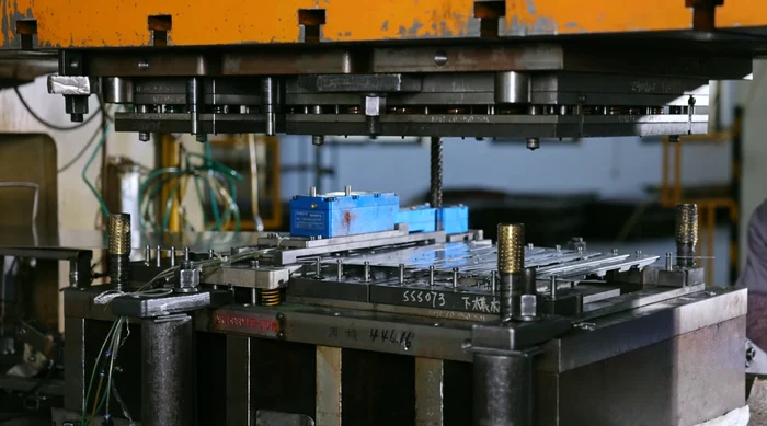
When an OEM buyer sends us a TV-mount bracket or a monitor-arm base and asks whether it should be stamped, the answer is rarely a single yes or no. Stamping becomes relevant when the geometry is largely sheet-based, the same part repeats across a program, and the features can be produced in a tool rather than fixtured one at a time. What the drawing shows about material, hole patterns, and formed features is what moves the part toward a progressive or compound die, toward laser cutting with secondary forming, or toward a mixed route. The three questions below are the ones our engineering team works through when it reads a new mounting drawing.
Does the material and finish callout support a stamped part?
Sheet grade and thickness sit at the front of the decision because they set what the die has to do. A cold-rolled steel wall plate, a stainless VESA adapter, and an aluminium arm cover behave differently under the same bend, and the drawing needs to say which one is intended rather than leaving the substitution open. Thickness matters twice over: it shapes the tool and it shapes the finish, since a heavier gauge changes how edges and burrs are treated before coating.
The finish callout is part of the same question. A powder-coated black wall bracket, a bright plated hardware piece, and a brushed visible arm surface each place different demands on the blanked edge and on how the part is handled between operations. If the drawing marks a face as cosmetic or as visible after installation, that changes how we plan the strip layout so the witness marks fall where they will not be seen. Where the material or finish is left open, quantity and tooling assumptions cannot be fixed either, and the quotation would carry an assumption instead of a decision. ThunderTech can review the material and finish callouts against the intended product family and confirm the workable options in the quotation.
Do the interface patterns repeat closely enough to justify a tool?
Mounting products are defined by their interfaces. A TV wall mount has a VESA pattern on one side and a wall or stud pattern on the other; a monitor arm has a clamp or grommet interface at the desk and a quick-release plate at the display. Those patterns are the features most sensitive to position, because they must line up with parts made on other tools and with hardware the buyer may already have standardized. When a drawing shows a stable pattern that repeats across several SKUs in the same family, one tool can often serve more than one part, and that is usually where a stamped route starts to make sense to review.
The opposite case is just as informative. If the pattern varies between revisions, if the buyer is still testing hole positions, or if the same plate is expected to serve several display sizes with different slot arrangements, committing to a hard tool early can lock in geometry that is not settled yet. In that situation our team may propose a route that keeps the flat pattern flexible until the interface is frozen, then revisits tooling once the drawing is stable. Either way we need the revision number and the tolerance on the pattern, not only the nominal dimensions.
Which formed features do you need the tool to produce?
Bends, flanges, ribs, extruded holes, and countersinks are where a mounting part stops being a flat blank. On a wall plate a return flange may be there to stiffen an edge; on an arm bracket a formed boss may exist so a pivot sits at the right height. Each of these features has to be reachable in the die sequence, and features that sit too close to a bend line, to an edge, or to each other can be difficult to form in one tool even when they look straightforward on the flat drawing. Welded or riveted subassemblies raise a further question, because the drawing then describes a joined product and the stamped portion is only one input to it.
This is why we read the formed features together with the assembly drawing rather than in isolation. A feature that is easy in the part may be awkward once the part is welded to a tube, coated, and then paired with hardware in the same carton. Where a feature looks difficult, our team will normally propose a DFM comment, for example an adjusted bend relief or a repositioned hole, and ask whether the change is acceptable to your design before the route is fixed. Product form and route details are confirmed in the quotation, not assumed from the flat pattern alone.
What to send before we quote
The items below are what let our team read the drawing as a manufacturable program rather than as a shape. You can see the mounting product families we build against on our TV mount and monitor arm product range, which helps confirm which family your part belongs to before we start the review.
- 2D drawing and 3D file with the current revision marked
- Material grade, thickness, and any acceptable alternates
- Finish specification and which surfaces are cosmetic
- Interface patterns with tolerances, including VESA or clamp dimensions
- Assembly drawing and hardware list if the part is welded or joined
- Annual quantity or forecast and batch size
- Inspection requirements and any customer-specific quality documents
- Packing format and carton or master-carton requirements
Send these requirements so we can confirm the program details, including whether stamping, laser cutting with forming, or a combined route fits your part. ThunderTech will review the drawing, return DFM comments where a feature needs discussion, and set out the confirmed product and route details in the quotation.
Tooling: the commitment behind the unit price
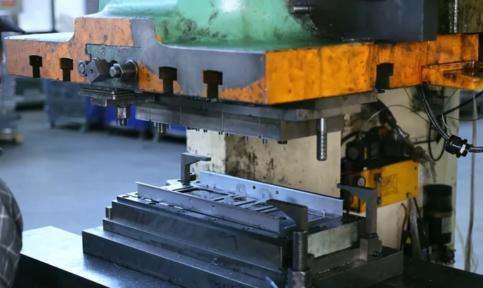
A quoted unit price for a TV wall mount bracket, a monitor arm base plate, or a stamped VESA adapter is only meaningful alongside the tooling assumption behind it. Progressive dies, form tools, welding and assembly fixtures, and finishing racks are built around a specific drawing revision, a specific material and thickness, and a specific expected pattern of releases. When any of those move after the tool is cut, the tool has to be reworked or supplemented, and the commercial basis of the original quotation no longer holds. Treating tooling as a separate decision from price is what keeps an OEM mounting program from drifting.
Is the drawing revision stable enough to cut steel?
Tooling turns a drawing into a physical constraint. A hole pattern on a wall plate, a pivot boss on an arm, a tilt-slot geometry, or a stiffening rib is inexpensive to change while the part is still a file and expensive to change once a die exists. The difficulty is that mount and arm drawings often reach the manufacturer while the interface is still open: the VESA pattern set is not final, the cable-management cutout is a placeholder, or the extrusion profile for a gas-spring arm is still being compared against an alternative. Cutting tooling against a revision that is expected to move converts an engineering question into a tooling change order.
The practical resolution is to separate features that are genuinely fixed from features still under review, and to agree which of the open ones the tool must be designed to accommodate rather than assume. ThunderTech can review the drawing and the revision history and mark where the geometry is tool-defining, so the open items are settled before commitment rather than after. Where a feature cannot be frozen yet, our team can discuss whether a soft-tooled or sampling route is appropriate for the first phase and what would need to be true before hard tooling is proposed.
What do the forecast and the variant list actually ask the tool to do?
Tooling scope is driven less by the annual number than by how that number is split. One fixed mount SKU released in steady batches asks something different of a die than a family sharing a common wall plate across fixed, tilt, and full-motion versions, or a monitor arm offered in clamp and grommet mounting with two finish options. A shared base part may justify common tooling with variant-specific secondary operations; a family where each version changes a load-bearing interface may not share as much as the SKU list suggests. Reading the forecast without the variant map usually overstates how much tooling can be consolidated.
What changes the decision is the relationship between variants, not their count. Where variants differ only in a downstream operation such as a bracket weldment or an added slot, the tooling conversation is about fixturing and secondary steps. Where they differ in the formed geometry itself, separate tooling may be the honest answer even when the parts look related on a drawing sheet. Send the SKU list, the variant relationships, and the forecast shape, and our team can plan a proposed tooling scope against them.
- SKU list with the variant relationships marked, not just the part numbers
- Forecast shape: expected release pattern and phasing, plus any planned SKU additions
- Which interfaces are shared across the family and which are variant-specific
- Finish and material options that may require separate handling
Who owns the tooling, and how are changes controlled?
Tooling ownership and change control are commercial terms, not paperwork. Ownership determines who holds the asset, what happens to it at the end of a program, and what documentation follows it. Change control determines what happens when a revision arrives mid-program: whether the change is treated as a rework of existing tooling or as new tooling, who approves it, what sample and approval step follows, and how the running SKU is handled while the change is implemented. Programs that leave both undefined tend to discover the gap at the least convenient moment, when a revision is already urgent.
These points are easier to settle at quotation than to renegotiate later. ThunderTech can confirm the proposed ownership arrangement, the change-control and sample-approval steps, and how a revision would be routed once a program is running. Where a buyer has an existing tool or an incumbent arrangement, our team can review what exists and discuss what would be needed to run the part, rather than assuming a transfer is straightforward. More about how we work with OEM programs is available on our company background page.
Before a tooling position can be quoted, ThunderTech would need to review the drawing and revision, the material and thickness, the finish requirement, the SKU and variant list with the forecast shape, the inspection and quality-plan expectations, and the packing requirement. The actual tooling scope, manufacturing route, production site, capacity allocation, and timing are confirmed in the quotation.
Where stamping ends and the rest of the route begins
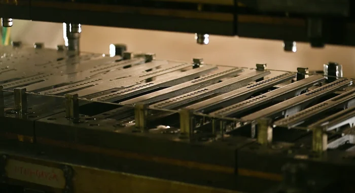
A stamping price and a delivered-part price are different numbers, and the gap between them is scope. Welding, finishing, subassembly, and packing each add operations, handling, and inspection points, and each one can also change how the stamped part itself must be developed. So the quotation depends on how far down that route the buyer is asking us to go, and an RFQ that stops at the blank cannot be compared with one that ends at a cartoned subassembly.
To quote the route rather than just the part, state the following in the RFQ:
- Whether the part is delivered as a loose stamping, a welded assembly, or a fitted subassembly, and if assembled, which components are included and who supplies them.
- Whether welding is in scope, at which joints, and what the drawing requires at those joints.
- The finish called out by name and colour reference, which surfaces it must cover, and which areas must be masked or left bare.
- Whether fasteners, bushings, gas springs, plastic parts, labels, or manuals are to be included, and at whose specification.
- The packing level required: bulk, inner carton, retail carton, printed artwork, palletisation, and whether cartons carry your brand or ours.
- Which of these steps carry documentation or record requirements, and what quantity or forecast each price should be based on.
ThunderTech can review this scope with you and discuss which route fits the drawing and volume you have. The site, operations, external processes, records, capacity, timing, and packing that apply to your program are confirmed in the quotation, not assumed from a scope list.
Quality planning that matches the part, not a template
A generic inspection checklist can be attached to almost any mount or arm drawing, which is exactly why it rarely protects the program. A tilt bracket, a gas-spring monitor arm, and a ceiling column fail review for different reasons, and the features that matter on each are not the ones a template happens to list. Quality planning becomes useful only when it is written backwards from the specific part: which features carry the interface, which are cosmetic, and which are simply nominal dimensions that no one will ever measure.
Which features on this part are actually critical?
Not every dimension on a drawing deserves the same attention, and treating them equally usually means the important ones get the same brief look as the unimportant ones. On video-display mounting products, the features that tend to drive review are the ones that must mate with something else: VESA hole patterns and their positional relationship, pivot and hinge bores, weld locations that set squareness, thread callouts on fasteners the installer will touch, and the visible surfaces that carry the finish.
The risk of leaving this undefined is that criticality gets decided informally at the bench rather than agreed in advance. If a buyer marks nothing, the drawing tolerance is all anyone has to work from, and a feature the buyer considers functionally critical may be treated as an ordinary dimension. ThunderTech can review the drawing and revision to identify which features look interface-bearing for the product form in question, and confirm in the quotation which characteristics we propose to designate as critical for that specific part. Where a buyer already maintains its own critical-characteristic list, our team can work from that list instead of proposing a parallel one.
What evidence should the inspection plan produce?
Designating a characteristic is only half the decision. The other half is what record proves it was checked, and that depends on how the feature is measured and how the part is made. A hole pattern held by a stamping die behaves differently under review than a bore located by a welding fixture, and the evidence that makes sense for each is not the same document. Buyers also differ in what they need to receive: some want a first-article report and nothing further, others want ongoing records tied to each shipment, and others need dimensional data in a format their own quality system can ingest.
Leaving the evidence question open is what produces disputes later, because the part may have been inspected in a way that was reasonable but not in the way the buyer expected to see documented. It is better to fix the record format before tooling than to reconstruct it afterward. Send the drawing and the quality requirements so our team can review what measurement approach the features allow and confirm the inspection and record arrangements for the program in the quotation.
What belongs in the RFQ so the plan can be quoted?
Quality planning cannot be priced or scheduled from a part drawing alone. What our team needs is the drawing plus the surrounding conditions that determine how the part will be verified and by whom. Where those inputs are missing, any quality plan attached to a quotation is a placeholder, and comparing it against another quotation built on different assumptions is not a like-for-like comparison.
- Drawing and revision level, with any critical or key characteristics already marked
- Material and finish specification, including how finish appearance is to be judged and on which surfaces
- Quantity and forecast, since the review cadence a buyer expects differs between a first build and a repeating order
- Required documents: first-article format, dimensional records, material or finish certificates, and who signs them off
- Any buyer-specific procedure, sampling standard, or acceptance criteria we should plan against rather than propose
- Packing and labeling requirements, where an inspection step is expected before or during packing
- Whether third-party or buyer-side inspection is planned, and at what point in the build
With those inputs in hand, ThunderTech can review the part against the proposed manufacturing route, plan a quality approach written for that part rather than copied from another program, and confirm the specific records and inspection arrangements as part of the quotation.
Bringing it to ThunderTech
Stamped brackets, plates, and knuckles for those products are among the parts our engineers can review, which is why we ask for the assembly and route information above rather than pricing a profile in isolation.
Send the following and our team can review it and come back with questions and a proposed program route:
- Part drawing plus the assembly drawing or parent SKU, with revision numbers and date.
- 3D file if available, and a note on which features are functional interfaces.
- Material specification, thickness, and any grade substitution you will accept or refuse.
- Finish specification, colour reference, and masking requirements.
- Scope of supply: loose part, welded assembly, or subassembly, and the component list if assembled.
- Quantity for first order and any annual forecast or release pattern.
- Inspection and record expectations, including any first-article or dimensional report you want defined.
- Packing and labelling requirements, destination, and target timing.
- Existing tooling status, if any, and whether it can transfer.
Send the requirements and we can confirm the program details in the quotation.
Questions OEM teams ask about stamped mounting components
What should a controlled drawing package contain before we discuss a stamped TV-mount or monitor-arm component?
Send the drawing at a stated revision level with the dimensions and tolerances you intend to hold, the material and thickness you have specified, the finish you want on visible and hidden faces, and any feature you treat as critical to the assembly interface. ThunderTech can review that package against the stamped part and the mount or arm it belongs to, and discuss which features need clarification before anything is committed; the quotation confirms the actual production site, in-house operations, external processes, tooling, records, capacity, timing and packing.
How much specification and forecast detail do we need to give at the discussion stage?
Alongside the drawing, describe the SKU or program the component sits in, the specifications you have already fixed versus the ones still open, and the quantity you expect per release together with the forecast horizon you are working to. ThunderTech can review those inputs and discuss how the stated revision, finish and volume expectation affect the route proposed for your program, with the quotation confirming the actual site, operations, external processes, tooling, records, capacity, timing and packing.
What quality-plan information should accompany the drawing and forecast?
State the dimensions or characteristics you want measured, the sampling and documentation you expect at first article and in production, the appearance standard for finished surfaces, and the packing format the component must arrive in for your next process. ThunderTech can review these requirements against your drawing and discuss how they would be reflected in the inspection and record set for the component; the quotation confirms the records, inspection arrangements, tooling, capacity, timing and packing that actually apply to the order.